Shafts of the Wastewater Pumping Station North Jeddah, Saudi Arabia
Design and Construction of the Shafts
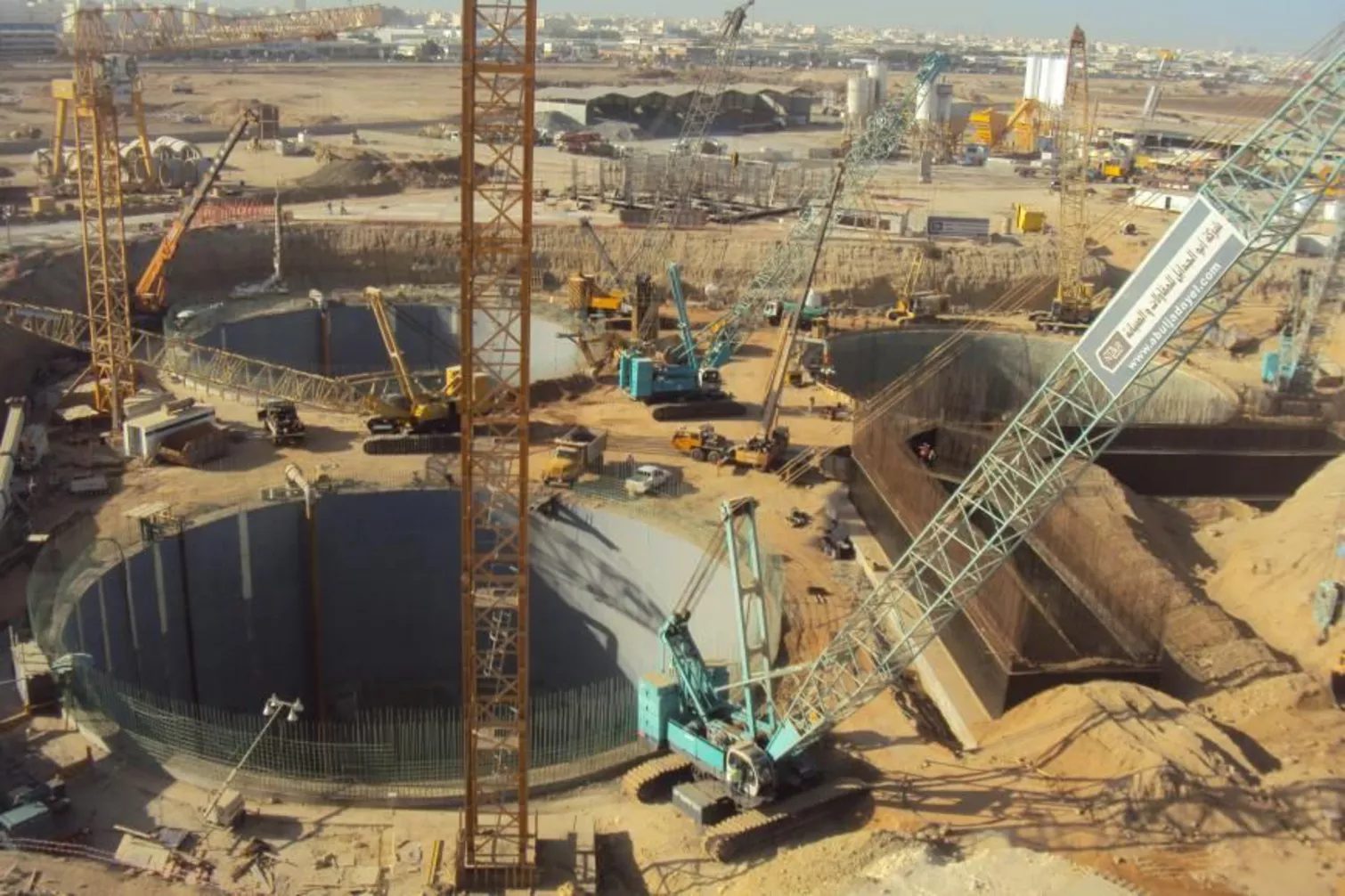
As part of an engineering community, Gruner Stucky Ltd was commissioned to plan the construction of a wastewater pumping station in Jeddah. The company Abuljadayel Co. For Contracting and Maintenance was tasked with building a new wastewater pumping station to the north of Jeddah, Saudi Arabia. As part of this project, three shafts have been constructed, each of them reaching an impressive final depth of 80 meters. Two of the shafts will be used as pump shafts, while the third will be equipped as a monitoring center with state-of-the-art technology. This makes them among the deepest shafts in the world, setting new standards in engineering that require innovative approaches for high-level design.
The challenges of this project are diverse and demanding: the final depth of 80 meters and a diameter of 40 meters each exceed previously achieved limits. At the same time, difficult ground conditions with a high groundwater table require special care and expertise. Gruner Stucky Ltd conducted detailed investigations and planning and was responsible for the development of the construction plans. The focus was on the development of an optimal design that meets the extraordinary demands.
In parallel, Gruner Stucky Ltd carried out the full design of the hydraulic structures associated with the pumping station, including the hydraulic dimensioning of pipelines and pumping chambers, the development of technical specifications for the hydromechanical equipment, and their integration into the overall design. Particular attention was given to the configuration and layout of the hydromechanical systems to ensure safe, reliable, and efficient operation under all operating conditions.
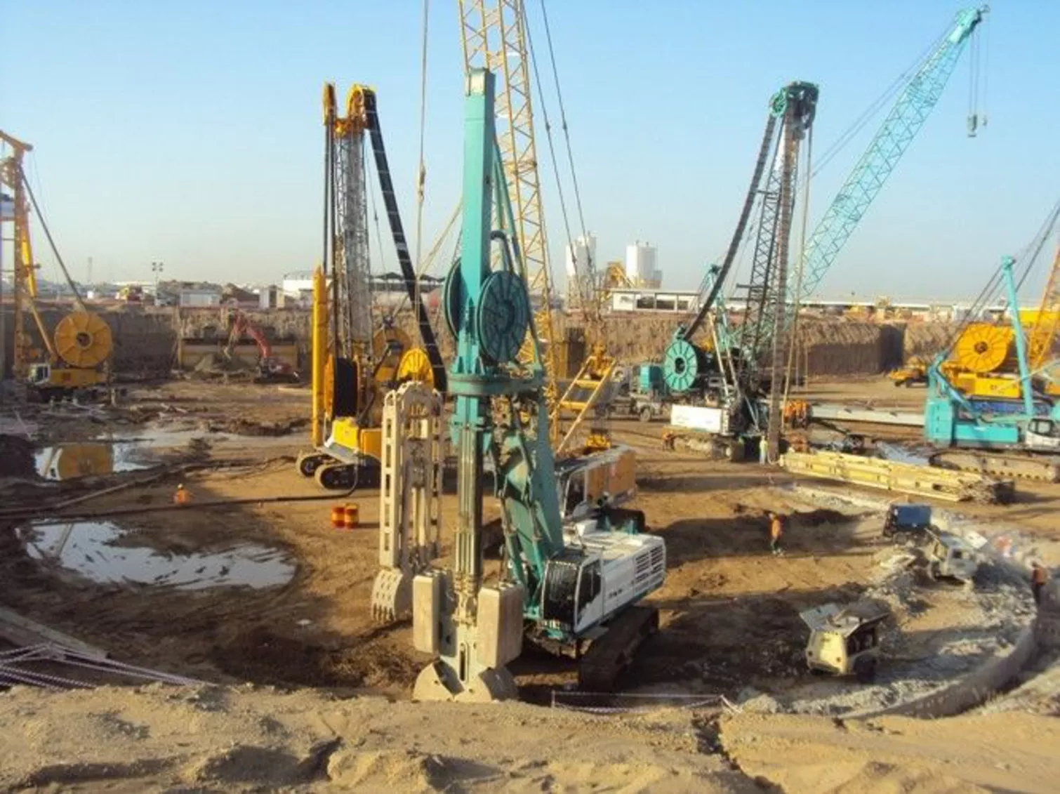
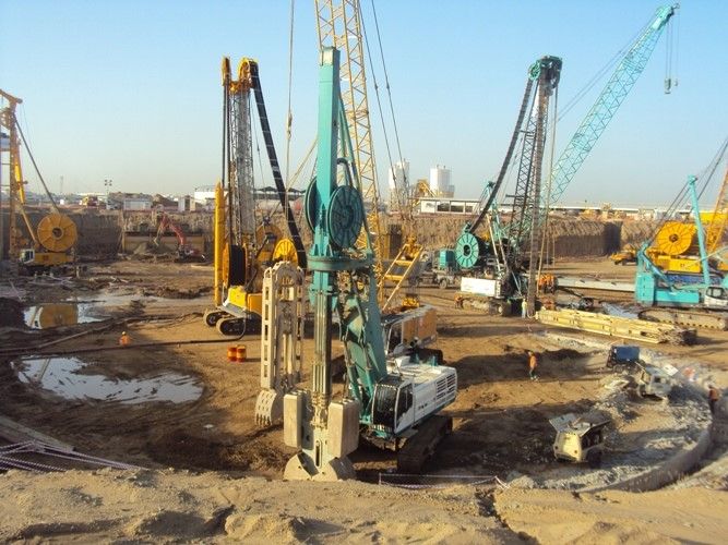 For softer soil layers, various diaphragm wall grabs were employed. For harder rock, diaphragm wall cutters were also utilized.
Key elements of the planning and optimization include:
- Numerical modeling of the structure and soil properties for precise analysis of the foundation.
- Evaluation of different design variants and development of the final optimal design.
- Design and planning of the hydromechanical equipment to ensure the functionality of the facilities.
- Development of the execution plans for implementation.
The shafts were constructed under the protection of a 1.2-meter wide, 95-meter deep diaphragm wall, whose stability is ensured by the base slab, several intermediate slabs, and multiple ring beams. The design considered various excavation states, flow analyses, and structural investigations of the diaphragm walls and the internal structures.
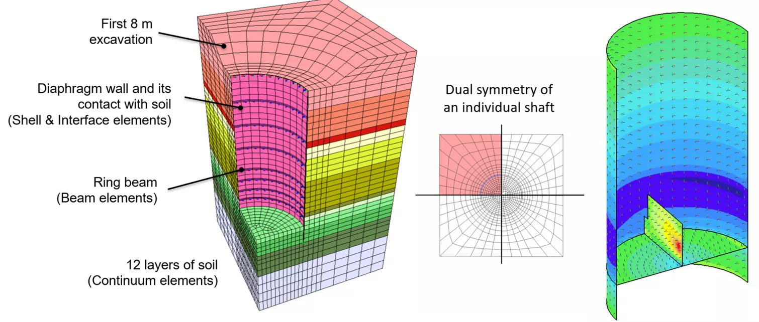
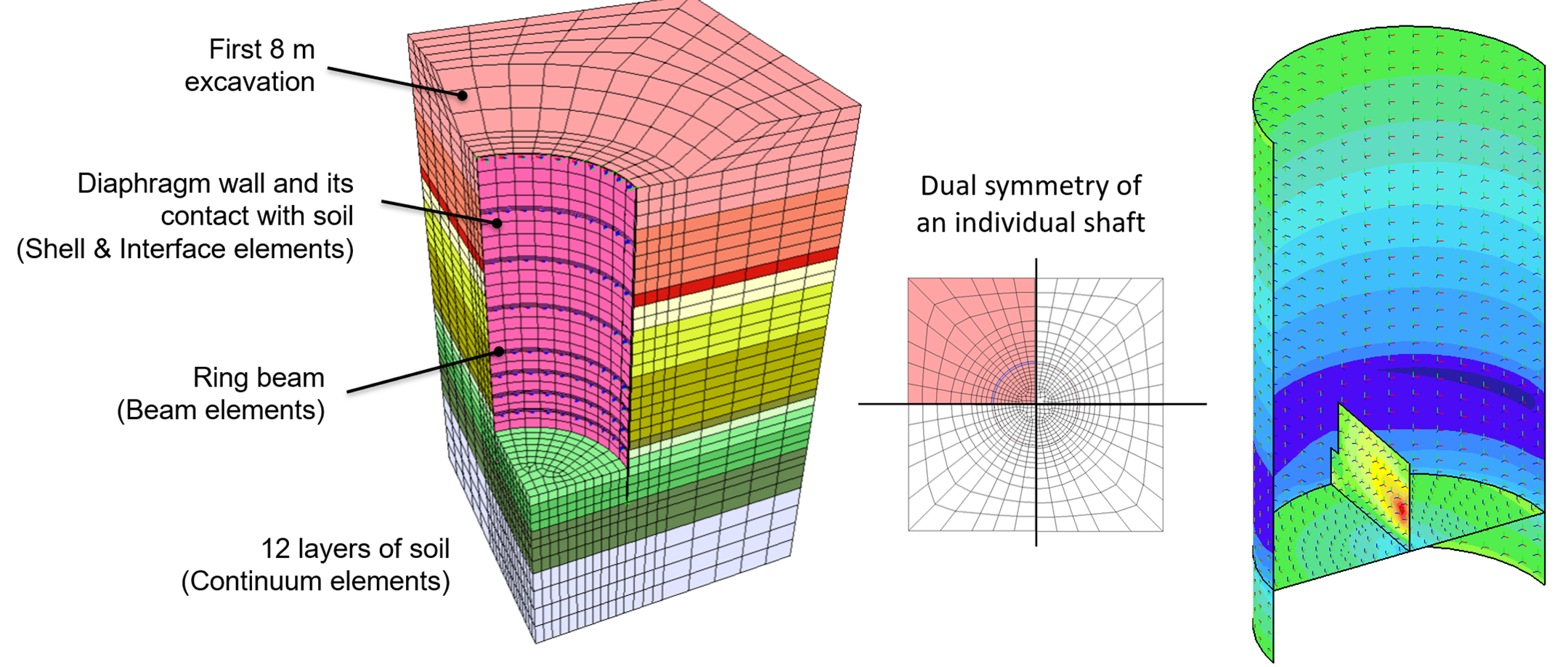 FEM model of a shaft (Dual-Symmetric View) and analysis of forces acting on the structure.
A dual-symmetric FEM (Finite Element Model) was used for the analysis, which includes not only all structural properties of the shafts but also twelve different soil layers. This model enabled a coupled flow and deformation analysis to ensure the safety and functionality of the construction. The implementation followed a semi-top-down method, which includes the following steps in this order:
- Excavation and concreting of the diaphragm walls (primary and secondary panels) from the top of the terrain.
- Gradual excavation and construction of permanent support structure elements from top to bottom.
- Construction of the base slab.
- Construction of the internal structures.
In addition to the planning requirements, several conceptual challenges arose during the construction. One of the most significant was the assembly and placement of the reinforcement cages for the diaphragm walls. Special care was required during the placement of the cages to ensure their stability. A special lifting device was used to ensure the vertical positioning of the diaphragm wall cages. The cages were first placed horizontally on the device and then slowly raised to the vertical position. Equally challenging was the placement of the 76-meter-long diaphragm wall joint elements, which required a high level of precision.
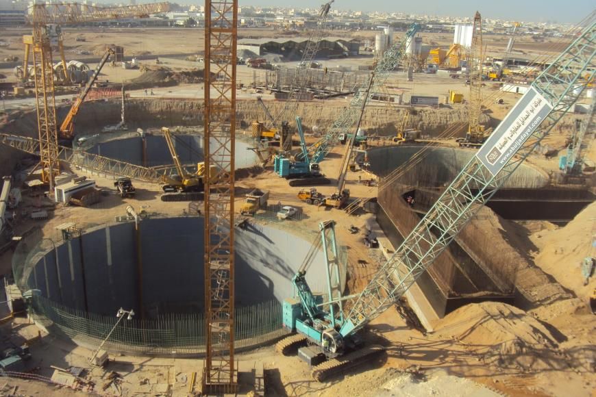 Overview of the Overall Situation of the Three Pumping Shafts
Another key aspect was the material management. The deployment and removal of heavy construction equipment, as well as the excavation and transportation of material, had to be precisely planned and continuously monitored. These processes were essential to ensure the smooth progress of the project.
Services
- Final Design
- Foundation and Geotechnical engineering
- Structural engineering

